 Sometimes an upgrade comes about through necessity rather than looks or performance it seems. I moved out to West Oxfordshire last year and that has not only increased my commute to work, but also reintroduced me to the trials and tribulations of travelling through the countryside – especially at dawn/dusk. This seems to be the time that deer, foxes and badgers are active and at the same time, idiotic commuters are using the 60mph limit as a minimum while thrashing through the dark, damp country lanes. The quantity of dead muntjac deer being testimony to the number of collisions. Of course hitting any of these animals on a bike will probably end with the rider experiencing the unique texture of the road surface at first hand.
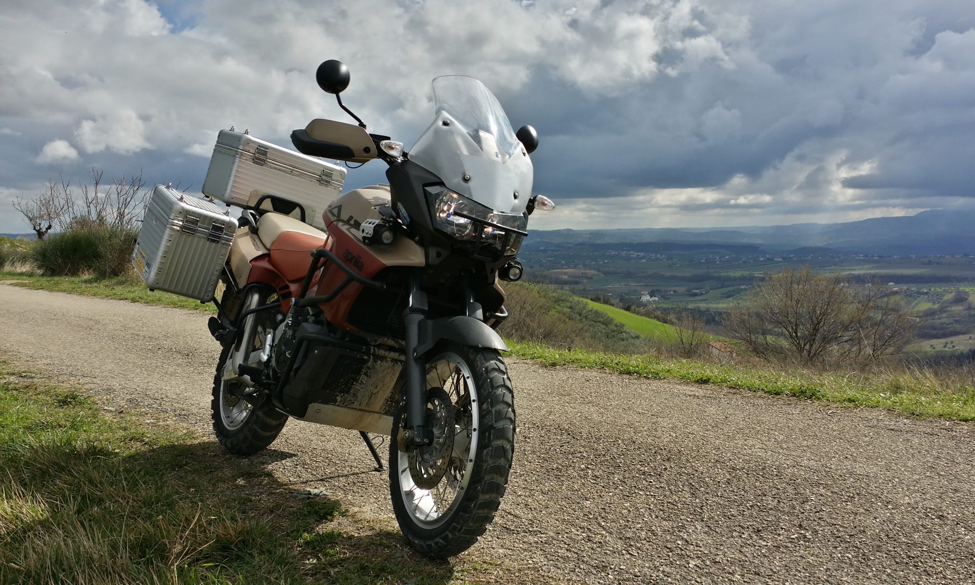
This meant it was a good idea to upgrade the old 55W H3 bulbs in my auxiliary lights to something LED and more economical on power. The Hella MicroDE’s were fitted way back when the Caponord actually had pages in the Touratech catalogue …. about 2010 as I recall. The down side has always been that they use a whopping 110W when lit and the Capo has never really been happy with that extra draw, plus the yellow light looks so dated next to the crisp white light from the LED headlights. Last time I looked the available LED H3 bulbs were pretty thin on the ground and frankly, more decorative than useful. In 2025, that seems to have all changed massively and I soon found a pair of LED bulbs that used GC7535 components at a reasonable price.

Sadly, as soon as I removed the rubber rear cover from the DE’s I knew I had a problem. The rear part of the halogen H3’s is a completely different shape to the LED’s and as such the retaining clip won’t fit. Out with the verniers, pad, pencil and fire up Solidworks and the 3D printer ……. a couple of prototypes and an hour or two later, I had two ASA-CF printed clips holding the LED’s nice and snug. Power draw is now approx. 2A each which is way less than previously and of course, the bright white light and spread pattern are simply way beyond what I had before.
The next morning I fired up the Capo at 06:00 and off we went into the crisp cold dark morning with (for once) no cars ahead or behind as I hit the Buckland road. Leaving the village, I fired up the lamps and rode at a comfy 50mph in the middle of the road, confident that if anything moved into the road within the amazing spread of light, I would be able to brake and (hopefully) avoid an impact with mother nature. It was also reassuring to see that the Capo was quite happy with the lamps on – voltage remained over 13.8v and the SparkBright battery-monitor lamp stayed green throughout. A win-win in my books!
So on the one hand, the Capo is winter-ready in the lighting department, but in truth will head back into winter storage by the end of November. But what it has done is make me acutely aware of the incoming shift in the type of riding environment and the changes I need to make on the winter bikes. Next up then, new lights for the Kawasaki ZZR1200 – Black Beauty!


 Secondly, the button/LED replacement I made. Here’s a breakdown of the existing button – just a momentary push-to-make switch and a red LED, nothing more. As mentioned in the previous post, the voltage to the switch is 3.8v and to the LED 1.8v pulling approx. 11ma. The switch could easily be replaced by any momentary switch you like, that’s easy, unfortunately though the LED is drawing very little current and so this line cannot be relied on (without frying something!) to power a brighter LED that would typically draw around 20-30ma, so a new circuit is required. Now this could be as simple as using this line to drive a transistor such as in the diagram below. Here a fused switched 12v line provides the required


 accommodate the twin indicator repeaters has had no impact, positive or negative. The voltmeter has been a different kettle of fish …. generally unused as the
  The second anniversary, although shorter at 6 months and a tad over 11K miles, is the
 Yes I admit it here and now, I’m doing a U-turn – a full 180° – and
  happened without the dashboard repair service. This year I opened the card and felt a twinge of regret, uneasiness, a sense that a decision I was making was the wrong one. The bottom line is that I would miss the emails/calls and involvement if I stopped something that I’ve been involved with since the beginning of unravelling the dashboard circuits.


 I switched on the fog-lights to better illuminate the mud and stone strewn road ahead; when it dawned on me that I hadn’t taken the Capo out in the dark for ages, months probably. And here I was winding a path along our troubled road and hopefully onward for a nice little night-time ride all in the name of testing the auto-dimming backlighting!
 In the end I was really pleased with how the lighting worked anyway, the only change I made was to the minimum brightness – dropping it slightly – so that it’s totally readable without putting stress on my tender night-time vision. Daytime backlighting is, as you would expect fully-on at 100% while the night-time drops to 30%, which with the higher output LED’s (blue & green) is just about spot on.
 being dipped in a coloured dye. Why? Simply that the humble incandescent bulb fires out light at all different wavelengths from infra-red to ultraviolet, so a simple filter is all that’s needed to allow the required wavelengths to pass through.
