
As this is to be a more detailed piece on how I accessed the Caponord ECU, I have moved away from generic posts to a dedicated couple of pages where I can elaborate in more detail about the route I took. This first page concentrates on the actual connection and cracking the security to gain access to the required data in the ECU.
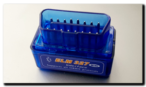 To access the ECU we traditionally use a USB to OBD cable and TuneECU (free download) on a Windows laptop, a good example of the cables required are the ones provided by Lonelec – a USB/OBD cable and adapter lead to connect to the diagnostics port on the Caponord. The other route is to use a generic ELM327 OBD Bluetooth module and TuneECU app on a smartphone. This does away with a cabled connection and is really nice when travelling – no cable or clunky laptop to carry. For my experiments I used the ELM327 adapter as I wanted to be able to intercept the serial data sent to/from the Bluetooth module.
This was my workflow:
- Attach the ELM327 Bluetooth module to the Lonelec adapter and plug into the Caponord diagnostics port.
- Turn on the Caponord Ignition
- Pair the ELM327 Bluetooth module with the smartphone
- Start the TuneECU app and connect to the ECU via the paired Bluetooth module
Data should now start to be displayed in the app. A good place to see this is the ‘Sensors’ page – simply use the drop down list to select a bunch of sensors you would like to look at. Later I will come back to this page as it is by far the most useful when trying to match data type with data on the serial port. This is my baseline – I now I have a working ELM327-Bluetooth-App combination. Now it was time to get under the hood!
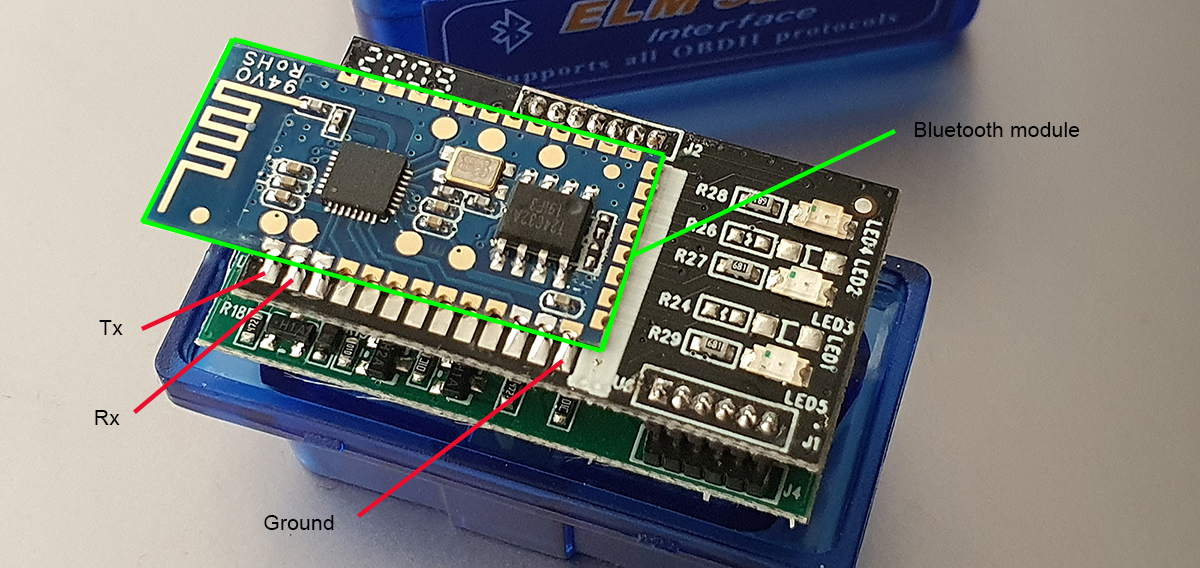 Some of these ELM327 dongles are glued together, but on this one, the lid simply popped off, saving me a lot of hassle cutting it off with a Dremel. Now the Bluetooth module is clearly visible piggybacked onto the ELM circuit board. The module has a whole host of solder points, however they only solder a few of them, saving you and me lots of work. The image alongside (click on it for a bigger image) shows the pins that I was interested in ….. Data Tx, Rx and Ground.
Serial data flows in one direction only, from the Tx pin to the Rx pin, so with connections made from Tx to Rx in each direction we have bi-directional communication … the app can send requests to the ECU and the ECU can respond on the other line – now all I had to do is listen to the data traffic on each of those lines. To do this I soldered a wire onto Tx, Rx and Ground and ran them to a corresponding Rx, Tx and Ground on an Arduino Nano. The Aduino is plugged into a USB port on the laptop and should be blank – no code running on it, especially anything using the Serial port or it just will not work. Now I could have just used the Serial terminal from the Arduino IDE to look at the data, but it’s not very nice, nor could I save the data for later analysis. Instead I downloaded a program called Megunolink, this makes viewing the data much easier PLUS I could record the data to a text file.
In Megunolink, like any serial terminal, you need to make sure that you are looking at the appropriate port (Arduino in this case) and that the Baud rate is set to 38400 not the generic 9600 or the received data will be garbage.
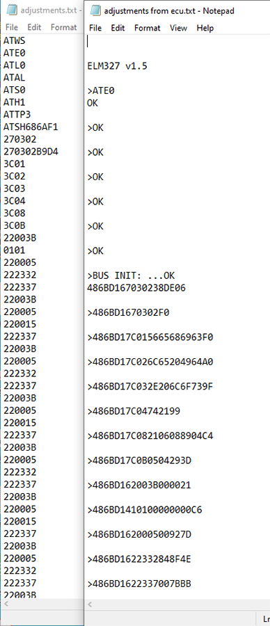 As the connection is established data should be recorded as in this image. It shows two instances of Notepad displaying data flowing in each direction to/from the ECU. Each was recorded independently.
OK, all well and good we have data but what the hell does it all mean? Lets start by clarifying a few things first. The ELM327 chip can receive commands that allow the user to change certain parameters regarding how it will handle data. These commands are ‘AT’ commands and as you can see there is a list of them at the start of the data flow. In exactly the order TuneECU sends them, they are:
ATWS Warm Start – a partial reset of the ELM327
ATE0 Echo off. Without this every request you issue will be echoed back wasting time and bloating the amount of data flowing
ATL0 Linefeed off to reduce transmission time
ATAL Allow long messages
ATS0 Remove spaces to reduce transmission time
ATH1 Set header to on
ATTP3 Use ISO9141-2 protocol
ATSH686AF1 Set the header to 686AF1
So far so good. We now know that the ELM327 receives a set of instructions each time the app runs to establish communications in a format that the app requires and to minimise the amount of data bouncing around in an effort to speed things up. Fantastic, but I’m now going to digress for a minute to better explain what comes next, hopefully it will make sense.
To emulate the app I can now simply enter each of the AT commands into the terminal and look at the responses – it works. So combining this with the PID information from the Wikipedia page I might be justified in thinking the job is done. I’m in, so lets go grab data … let’s give it a go … I’ll type in the first PID:
(sent) 0100
(Received) 486BD14100BE1690113A
I have a response, cool! What I asked was (0100) ‘How many PIDs between 0100 and 0120 are used?’ The relevant part of the response is BE169011 – everything before that is the header 486BD14 and confirmation of PID entered (0)100 and the last two digits are the checksum of the sentence. Using the explanation of how to interpret this data from the wiki page, I can see that I have the following PIDS;
0101, 0103 – 0106, 0108, 010C, 010E, 010F, 0111, 0114, 011C and 0200
These are:
0101 DTC (errors)
0103 O2 – Open loop/Closed loop
0104 Load
0105 Coolant Temp
0106 Fuel trim
0108 Short term fuel trim?
010C RPM
010E Ignition Advance
010F Intake Air Temperature
0111 TPS
0114 O2 Sensor
011C OBD Standard
0200 List of available PIDs in the range 0201 – 0400
That is a great start, but already cracks are beginning to show ……… this is about a third of the data we know is displayed in TuneECU – where is the rest located? Well I scoured high and low through Service 01 and there is nothing above 0200. The other Service modes are not relevant to live data, so I was rapidly grinding to a halt. I did find some reference on the internet to manufacturer specific PIDs being located higher up in the 2000+ range, but nothing specific and was not about to start chasing ghosts. So there had to be something in the TuneECU data I had captured. And sure enough, I can see data transmitted and received between TuneECU and the bikes ECU like this;
Requested PID (O2 Output Voltage) 220028
486BD1620028005D6B – 486BD16 is the header, 20028 is a partial echo of the PID requested and the last byte is the checksum of the sentence: 48+6B+D1+62+00+28+00+5D = 6B. The data bytes are 00 5D, in this case 5D = 93 decimal and the formulae for this PID is A/200 ….. so 93/200 = 0.465 and this is the resting voltage from the O2 sensor.
Inlet Air Temperature 220004
486BD1620004003923 – 486BD16 is the header, 20028 is a partial echo of the PID requested and the last byte is the checksum of the sentence: 48+6B+D1+62+00+04+00+39 = 23. The data bytes are 00 39, in this case 39 = 57 decimal and the formulae for this PID is A-40 ….. so 57/40 = 17 and this is the Inlet air Temperature 17ºC
So it’s now obvious that the software is looking in a completely different location in the ECU than the one detailed in the Wikipage. OK, that’s easy then isn’t it? Well sadly, no. When I repeated the AT commands and then sent the same 20004 and 20028 PIDs, this is the response I got each time.
486BD17F3336
And I think this is a ‘Your not allowed this information’ kind of response. Obviously there was something else going on and I had missed it … so back to the initialisation responses. It was here that I noticed this:
(Sent) 270302
(Received) Bus INIT . . . OK
(Received) 486BD1670302ABCDXY These two bytes change every time connection is made – These are termed the ‘seed’ it turns out.
(Sent) 270302EFGH – Here two bytes are appended to the same PID and sent back to the ECU
(Received) 486BD1670302FO – This I think is a confirmation reply.
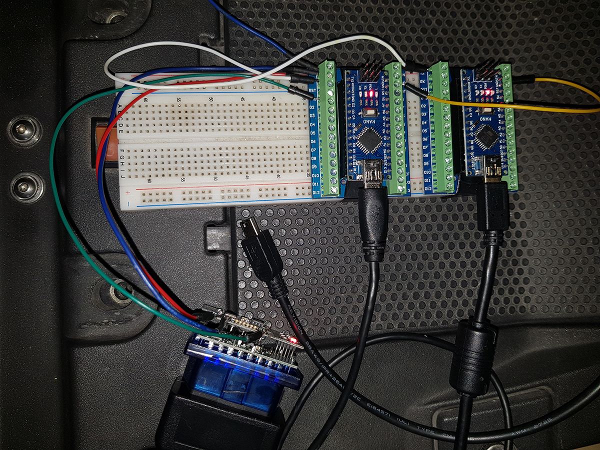 This is now where everything started to fall apart! I had been reading the data traffic to/from the ECU, one way at a time and ASSUMED that the ‘ABCD’ part was the same in each direction. I realise now, that that was a really dumb assumption as this would be some sort of security not just a happy-slappy handshake. So to confirm this I needed to be able to watch the data flow both ways at the same time. A fairly simple modification of the wiring and swapping to a pair of Arduinos and two instances of the serial monitor in ‘Megunolink’ to watch and record the data flow had everything working and so the investigation began. The first recorded ‘Seed’ from the ECU was 657B and the response sent from TuneECU was CBD3 ….. hmmm, no really obvious pattern – so I recorded more, about a dozen in all. With each one my heart sank a little lower as no pattern appeared to leap out at me. This was Sunday morning, a mere 12hours since my post and now I felt foolish for leaping to a conclusion that was so hugely flawed. Give up, or go on?
Well Sunday rolled into Monday and Tuesday and …. you get the picture. Most of my spare time was spent searching the internet for clues that might help and feeling more and more like I was on a fools errand. I tried so many ways of looking at the data it made my eyes hurt – still nothing. By Friday lunchtime, I had almost had enough and decided that the end of the day was the line in the sand. No more, at least for the weekend. Then a break. I found a piece on a fairly obscure website that gave me a couple of clues that turned out to be absolute gold and refreshed the desire to forge on. It was not so much of a U-turn, but more about not overthinking the problem!
I had a set of Seed data and I had a set of matching calculated responses ( ‘Keys’ ) …. what I needed to look for was a constant, a number and/or formulae common to both and to achieve this I needed to write a simple little program that used brute force to reverse-engineer the process. By 9pm on Friday evening I set it running – It was to run for about two hours and should, if everything worked, find me at least one instance of the constant. I had a look at about 11:30, the program had run its course and found ……….. zero instances. My knees were giving way, it was approaching midnight and frankly, I’d had enough. Where the next step came from I don’t rightly know.
The recorded file was opened in Notepad and although the program said there were no instances of ‘CBD3’ I ran a simple ‘find’ …………. and there were three! I cast an eye over the program I’d written and plain for all to see was a glaring fault in the code, it would find an instance, but not tell me in a month of Sundays! Back to the ‘find’ – two were not where I needed in the hex string, but the third was. This one occurred at the 26505 (decimal) calculation ………… and in Hex, 26505 converts to ‘6789’ and that number was just too none-random to be insignificant! Was this really it?
With a load of Seed/Key pairs to hand and minutes until midnight, I ran them through the transposition:
| Seed | Key | Calculated Constant |
| 8482 | 3792 | 6789 |
| F825 | AECD | 6789 |
| 016C | 36CC | 6789 |
| C19F | 9717 | 6789 |
| 73AA | 4BFA | 6789 |
So here it is then, finally, the simple bit of math that unlocks the ECU. Take the Seed, multiply it by the constant and return the modulo to leave the two byte Key. Here is a worked example with a known Seed/Key pair (657B/CBD3)
(Seed * 6789) % 10000
(657B * 6789) = 290A CBD3
290A CBD3 % 10000 = CBD3
In the end, looking at the generic (Wikipedia) 0100+ range of PIDs turned out to be a real red-herring and in fact the ECU needed to be unlocked all along to access a completely different area where the Caponord data is stored. Simple once you know! With this knowledge now well and truly in the bag, I closed the laptop and turned out the light and headed upstairs to bed happier than I guess I should have a right to be. This has been a long journey over several years with lots of wrong turns. Tonight I know I won’t sleep properly and I’ll pay the price tomorrow ….. but it has been worth it. Next up ……. Part2 – sorting the timing issues and decoding the response sentences.