Dashboard repairs

Risto's Christmas cardYes I admit it here and now, I’m doing a U-turn – a full 180° – and NOT stopping dashboard repairs at the end of January 2015. Jeez …. You’re thinking, I wish this chap would make his mind up!!

Why the change of heart?

A couple of reasons actually …. Firstly, a few emails over the past couple of weeks that have made me reflect on the initial decision, secondly a Christmas card. Yep – a lowly piece of card with a simple season’s greetings from a Capo owner in Finland.

Risto sent his board over almost 18 months ago and by all accounts is happy with the work done and each Christmas he has sent a card. That connection across the continent would never have Aprilia Caponord ETV1000 & Rally-Raid dashboard repairs and upgrades, backlighting and voltmeterhappened without the dashboard repair service. This year I opened the card and felt a twinge of regret, uneasiness, a sense that a decision I was making was the wrong one. The bottom line is that I would miss the emails/calls and involvement if I stopped something that I’ve been involved with since the beginning of unravelling the dashboard circuits.

Jan and I sat down and worked out some ways to free up a little more time and I’ve decided to put other projects on the back-burner for now. So I will not stop doing what I’ve done for almost two years ….. Give folks a grain of hope that a piece of their pride and joy can be repaired or upgraded. Sorry for the wobble, but hey, I’m only human.

And Risto ….. If you read this, just remember that opening your Christmas card changed the course of moto-abruzzo as he staggers into 2015. That’s pretty awesome when you think about it! 😀

New fault code

Aprilia Caponord ETV1000 Rally-Raid. A tacho .... but not just any old tacho, oh no. In fact if Carlsberg and M&S made tacho's......A few days ago while doing a bit of investigating for an AF1 forum member regarding the tachometer signal from the ECU, more specifically what would he observe on a multimeter instead of an oscilloscope, I momentarily shorted the tacho line against the chassis with the bike running. The tacho shut down and the bike just kept chugging along quite happily – no EFI light, no tacho. Recycling the ignition bought the tacho back to life and it’s been fine ever since ……… but two points came out of this that may be of use to other owners.

  • Check for a fault code with TuneECU – ‘P1386 Tachometer, open circuit or short to ground’ 
  • When the ignition switch is first turned on the Tacho line should show a solid DC battery voltage – if you don’t see this the ECU may well have shut down the output to protect it. Only once the engine starts will you see this signal:-

Aprilia Caponord ETV1000 Rally-Raid tachometer signal

Anyway, just a quick observation, a new (to me) fault code …. one to file away in the compendium of Capo facts. It certainly proves that the tacho signal isn’t just a ‘dumb’ signal, it’s one the ECU monitors and protects as neccessary by shutting it down.

Finger on the pulse

Aprilia Caponord ETV1000 Rally-Raid. Speedometer pulse from the rear-wheel sensorWhile the wrist is healing nicely on light-duties and (thankfully) out of the heavy and restrictive cast, I’ve had a chance to play with the idea of an active cruise control for the Capo. An active system will adjust the throttle automatically to maintain a given speed even as the road rises and falls unlike a passive system which is nothing more than some form of throttle locking mechanism.

Arduino cruise control sketch
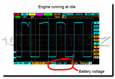
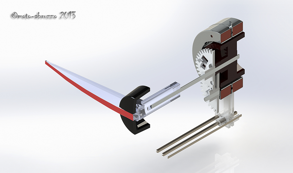
The system I’m thinking about will, when all parameters are met (speed, revs etc) lock onto the chosen speed when the ‘Set’ button is pressed. The microcontroller will then look at the error between the chosen speed and actual speed and adjust the throttle as neccessary to try and maintain the error at zero – this is done using PID (proportional-integral-derivative) in the controller. If cruise is stopped (operation of brake or clutch) or the PID error goes beyond a pre-determined maximum (high gear on a steep hill for example) the requested speed is stored and can be re-activated by pressing the ‘Res’ume button. And while in cruise, the speed can be adjusted in 1Kmh increments by using the same two buttons, now working as ‘Acc’elerate and ‘Dec’elerate. That’s the theory anyway!

Aprilia Caponord ETV1000 Rally-Raid. Opto-isolated and cleaned Speedometer input signalInputs

  • Power – 12v on/off switch
  • ‘Set/Acc’ &Resume/Dec’ buttons – 12v
  • Front and rear brake light switches – 12v
  • Clutch lever switch – 12v
  • Speedometer signal from the dashboard (output on pin 14 of the 16-pin connector) -12v square wave 85% duty cycle frequency modulated
  • Tachometer signal -12v square wave 50% duty cycle frequency modulated.

Honda GL1800 Cruise ServoOutputs

  • Two colour LED for power, cruise engaged & error codes – 5v
  • Motor drive signal – 5v PWM to motor control board.

To date the inputs and safety stuff has been written and from the tacho/speedo signals it’s calculating what gear the bike is in pretty quickly, but I’m sure it can be speeded up …… I just need to learn more programming! The operating parameters I’ve decided on are:

  • Cruise enabled between 50Kmh and 160Kmh (30mph – 100mph)
  • Cruise enabled between 2,750rpm and 6,000rpm but might change the lower limit to 3,250rpm in 6th gear
  • Cruise enabled in 4th, 5th and 6th gears only.

At the end of the day, I just want a system that will give my old worn out wrist a rest at motorway speeds on the run between Italy and the UK, taking into account the (very!) variable speed limits and ascents/decents especially through Switzerland. If it can do that I’ll be a very happy bunny indeed.

Of course this is all well and good, but I’ve got to get all the bits talking to each other first and make it robust enough for long-term and safe use on a motorbike ….. the problem is that in amongst all this enthusiasm my wrist still has a way of letting me know who’s really in control while swanning around on light duties!


Dimmer and dimmer

Aprilia Caponord ETV1000 Rally-Raid Evening over the Gran Sasso ....
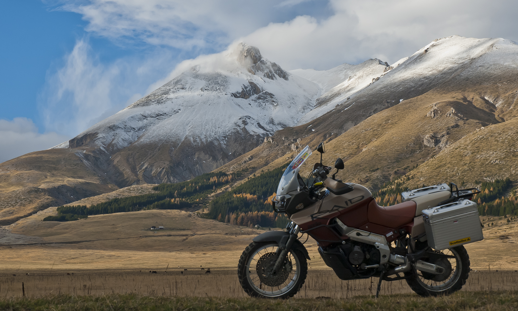
I switched on the fog-lights to better illuminate the mud and stone strewn road ahead; when it dawned on me that I hadn’t taken the Capo out in the dark for ages, months  probably. And here I was winding a path along our troubled road and hopefully onward for a nice little night-time ride all in the name of testing the auto-dimming backlighting!

After getting the set-up working nicely with the old thumb-over-the-sensor routine, it was time to take the old girl out for a spin and see what the illumination was like both in unlit rural and street-lit urban riding. I took the netbook and cable along so that changes to the code could hopefully be done at the roadside.

Aprilia Caponord ETV1000 Rally-Raid .... and over the Maiella.In the end I was really pleased with how the lighting worked anyway, the only change I made was to the minimum brightness – dropping it slightly – so that it’s totally readable without putting stress on my tender night-time vision. Daytime backlighting is, as you would expect fully-on at 100% while the night-time drops to 30%, which with the higher output LED’s (blue & green) is just about spot on.

But ……

And there’s  always a ‘but’ …… the two LED’s in the binnacle (Autoswitch & Battery monitor) now stand out as being overly bright compared to the dashboard at night, so, time to work out how to take these signals and pass them through the Arduino and subject them to the auto-dimming code as well, then the whole cockpit area will be sorted at last!  😉

New ‘Lockwood’ inlay fitted at last

Right indicator repeaterOn 4th February Jan came back home with a suitcase fair groaning with all manner of goodies. The most eagerly awaited though, was the pair of new inlays from Lockwood International Ltd. So first impressions?

Excellent! From the textured material to the bleed-free printing, from the fit to the light-transmission …. everything was exactly as I’d hoped. The first thing I did was pop one onto a waiting chassis/board and turn on the lighting – did the text and colour match the light channels? Again, perfectly. Now I could relax, prepare the new chassis and get ready to fit one permanently to the dashboard. To fix it in place I decided to use a general-purpose spray adhesive and did a trial run on an old chassis/inlay to make sure it would be suitable. Everything seemed fine and it was certainly good experience to do a dummy run.

Making sure the chassis was grease and dust free was essential, then masking off the light-channels, mounting pegs and anywhere else I didn’t want spray glue to go! A couple of thin coats of adhesive were applied and the inlay fitted 10 minutes later to allow time for the solvents to evaporate. Perfect! It was now ready to be fitted to the circuit board, but first a couple of modifications to the board/processor circuits.

First the eeprom file needed to be updated for the Futura speedo/tacho, then the code in the microcontroller needed updating for the different (voltmeter) needle calibration. At the same time a couple of modifications were made to the circuits based on insights I’d picked up about Arduino boards from the Internet, also the auto-dimming circuit was finally added for the variable back-lighting, a bit of tweaking with the code – and it was all ready to be refitted to the Capo.

So there I was …. on a wind-swept but warm Sunday morning, dashboard in hand and about to see the fruits of a few months work finally come together on the bike. No doubt the code for the auto-dimming will need fine-tuning, but that can be done without removing the dashboard again – and that’s the line in the sand, right there. Once fitted, I shouldn’t have to remove them again anytime soon …. and that’s a great feeling!

I think that about now would be a great time to pause and say thanks to a few folks who have helped me keep the momentum in this little project. Firstly Jan for her patience and for lugging stuff across the continent for me, to Andy (beasthonda) for bouncing ideas around with me and his interest in the project, to Arvdee in the USA without who’s generous donation of a Futura inlay I wouldn’t have had a template.  Last but not least, Clive from Lockwood International for putting the proverbial icing on the cake – thank you all!!!! 😀

Moving along nicely

Just got this photo from Clive over at Lockwood International in the UK, the nice folks who have made my new inlays for the Caponord dashboard. I’ll write more when they arrive …… I can’t wait!!

RST Futura based inlay with voltmeter and left/right indicator repeaters

  • Back-lit voltmeter within the tachometer
  • Left & Right indicator repeaters
  • Red-line raised to 10,000rpm to match ECU setting
  • Side-stand lamp is now where the unused ABS lamp was
  • Funky Aprilia lion instead of boring old ‘aprilia’ text
  • ‘magneti marelli’ logo removed …. well they didn’t design this one!

Reading the current situation

©Lockwood International 2014 - UK Futura inlay with voltmeter, L&R indicators and sidestand lightWith the new inlay nearly complete and sufficient testing of the modified dashboard to prove its reliability in day-to-day use, it’s now time to move on and complete the next stage of miniaturising the circuit board. The big grey box and wiring loom holding the Arduino Uno stays for the time being, but now it will house the smaller circuit board and Arduino Nano. Once thoroughly tested, the box and loom will disappear as the board finally gets mounted inside the case.

Aduino Nano and Pololu 1300 programmerThis time around the microcontroller will be programmed differently to speed up the start time and free up more memory space. For that I’m using a Pololu 1300 programming device ….. Something I’ve never done before, let’s hope I don’t fry it! If all goes well, that then leaves me an Arduino Uno spare and it would be rude not to find another Caponord related little job for it! So here’s the next project…..

I’ll be installing the Uno and three of these naughty little puppies along with and LCD screen into the redundant grey case. Self-powered, it will measure current flow through the 30A rec/reg fuse and the two main 30A fuses simultaneously. The screen will Pololu ACS714then display measured and calculated data as well as storing the data onto an SD card mounted into the display. So it’ll be a data-logger as well!

The idea is to have the three ACS714 devices, wiring loom and a single multi-pole connector under the saddle. The unit will then simply plug into the connector and merrily measure away. A decent battery and memory card should make data logging for 2hrs + pretty straight forward. So watch this space ………


See ya later Indicator

While it rains, rains and rains some more, I’ve had time to complete the mods with respect to moving the warning/tell-tale lighting around on the dashboard. Now the Capo has a nice left AND right indicator repeater lights ….. and looks all the better for it. So to recap.

  1. Unused ABS light is now the side-stand light
  2. The side-stand light is now the low-fuel warning light
  3. The low-fuel warning light has new green LED’s and is now a right-hand indicator repeater.

Here’s another piece of video with all the lights working. You’ll notice that the fuel is already on reserve, hence the old side-stand light (now low-fuel) is on throughout the video. Sorry about the quality, but a dismal dark day and a smartphone don’t work so well together ….. and my cold hands adding the shake didn’t help! I’ll add a new page to the site shortly with details of how the circuits were rearranged.

While I waited for Youtube to upload the video, I took a walk down the road to see what damage had been done by the 24hr+ of solid heavy rain …………

…………. let’s just say the Capo nor the Rangerover are going anywhere soon. We don’t appear to have a road left for about a 30m stretch. It appears to be languishing somewhere down in the valley by the looks of it! Pics tomorrow. 😥

Tacho/Voltmeter live on the Caponord

Up and running at lastPhase 1 is over, Phase 2 begins …….. yes, the reworked dashboard with voltmeter/tacho and fade-in/fade-out auto-dimming backlighting is off the workbench and finally onto the Caponord. I know it doesn’t look too inspiring at the moment, but it is only a prototype unit for development. The white tacho face is simply a temporary inlay printed on a piece of A4, so it better not get wet!

Arduino Uno V3Inside the box lives an Arduino Uno with a homemade interface board that switches and adjusts the signals to/from the dashboard as required. The single connector plugs into an additional fused loom that runs to the battery positive terminal. I’ve tried to build in safeguards against under/over voltage, battery disconnection and reconnection spikes and its own failure with regards to how the dashboard functions, hopefully most if not all eventualities have been covered …. fingers crossed!

The little grey box .... I’ll run this setup for a while and try to iron out any other issues as they crop up, but what then? Well Phase 3 has already started in parallel with Phase 2! A new microcontroller board that uses the same chip, but with a footprint that is an astonishingly small 8% of the Uno has been ordered. Not only is it small, it also loses the peripheral bits and bobs that I don’t need – and that means much lower power consumption. I’m really hoping to get the whole thing inside the dashboard case if possible, but the worst case scenario will mean a small box fixed directly to the back of the dashboard – so no wiring loom or bulky connectors!

Where the ideas originated ..... the Kwak GT & GPZ's of the 1980/90 eraAs well as getting the inlay reprinted with the added voltmeter graphic, I’ve also decided on a little  re-arrangement of the existing graphics and functions. For example, why oh why is a ‘side-stand’ light prime-center of the display when it already has a safety circuit to stop you riding away with the stand down? ….. Magneti Marelli over-egging the pudding I think.

So the side-stand is moving down to the (unused) ABS lamp spot, the low-fuel then moves up to the side-stand lamp and the low-fuel light then becomes the right-hand indicator – as it should have been all along. Yes, a turn repeater for both left AND right hand signals!!!

Left AND right turn repeater lamps!

With all this in the pipeline, I can now source a decent place to have the new inlay card made. I’ve spoken to a couple of companies in the UK already, but I’ll keep looking around for a little while longer …….. do you know anyone you can recommend? If so, I’d like to hear from you.

 Last but not least, here’s another short piece of video with the panel working on the bike.


Get yer motor running ……..

Aprilia Caponord ETV1000 Rally-Raid dashboard stepper-motorNo, not the mighty V990 Rotax, more the tidily-tiny stepper motor that runs the speedometer and tachometer. An unobtrusive little thing with a hefty replacement price tag of between £30-£50 each.

The B-0410-116-530 stepper motor is also used in a variety of cars from Audi, Fiat, Renault and Citroen. Anyway, I had a duff one on a board and decided to remove it and poke/prod/measure its internals for digital posterity. Here’s a couple of Aprilia Caponord ETV1000 Rally-Raid dashboard stepper motor -sectionimages of the little darling. I’ll be adding a Dashboard page shortly with lots more info on the motor and the circuit board along with plenty of ‘how to’ tips to hopefully save you a few bob on repairs by doing it yourself and avoiding the pitfalls that leave you with an expensive paper-weight!