
 Sorting the rear tensioner yesterday took all of 20 minutes, but I knew that the front was going to be a different kettle of fish altogether because of the coolant pipes. No worries, I thought – a good excuse to change out the coolant as well.
So in I went and oh what fun it was! Off with the crash bars, side panels and sump guard, move the coolant bottle and release the radiator bottom hose and drain the system – so far, so good. Remove the airbox and release the clamps holding the throttle bodies in the inlet rubbers ….. hmmmm – looks like they’ve got a few deep cracks I’m thinking.
 Take off the rest of the hoses, cables and electrical connectors, now a gentle pull and twist to release the throttle bodies and ……………… oops! I think the cracks in that rubber were a tad deeper than first thought and a touch beyond repairing with a splash of rubberised goo. Luckily I’ve a spare pair to hand from the l’Aquila stash. However, this momentry inconvenience isn’t the task of the day ….. so onward once more. Hoses, cables anything and everything moved so I could at last get to the two clamps holding the ‘Y’ hose in place – then finally the goal was in sight, the pot at the end of the rainbow …. the front cam chain tensioner!
 With a heave, a grunt and too many fingers trying to get into too small a space I managed to retrieve the tensioner from its hide-away, gave it a squeeze and ……… it was fine, solid as a rock! Never mind, a flush to clean out any debris and a refill with clean oil never hurt.
Then it was rebuild time. The tensioner’s in place and the cap torqued down to 30Nm with a swanky new copper washer. The super-shiny inlet rubbers torque down at 19Nm and the rest of course is then a reversal of strip-down – with the intention of NOT ending up with any washers, screws or clips left over! And so with the sun ready to slip behind the mountains it was test-time. Glad to say she fired up first hit of the button and sounded so much smoother, funny how you get used to little noises and ‘character’ over time – now she’s idling smooth as can be, a tweak on the throttle body sync screw had the manometer within a couple of mills AND it stayed that way when the motor was reved, something it didn’t do last week. So I’m guessing the cracked inlet rubbers were an issue after all! 😳 So that’s it for today, other than updating the Capo’s history spreadsheet ….. the Capo has now done a pinch over 74,400 miles and other than a couple of valve shims and plugs, it’s the only work the motor has ever needed.
Next stop – tyres, chain and sprockets. 😯
 Yesterday I spent a lazy morning installing a couple of sensors inside the airbox (more in another post) and with the tank propped back in place, fired the Capo up to check the fuel lines…….
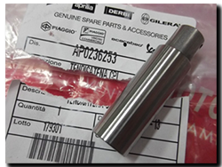 rear. As it was lunch time, I decided to have a look a bit later – and promptly forgot! Well I got back to it in the evening and pulled the cam chain tensioner out. Soggy as a knackered bed spring! 🙁
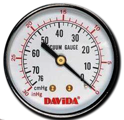 It’s been a while since the Capo was serviced and one job has still remained outstanding – in fact it has been ‘outstandingly’ outstanding for the past few services since I lost my old
  First off, what kind of vacuum are we looking at from the Capo motor? From measurements, it looks to be somewhere in the range of 22-24cmHg (based on an erratic Carbtune II) per cylinder measured against atmospheric pressure …. Now that’s not much for a mercury manometer – barely the length of a sheet of A4 paper. A nice compact manometer then, except that unfortunately mercury is almost impossible to get hold of because it’s deemed way too dangerous for us potato-heads to use safely. So what does this mean in terms of manometer height if we use liquids of a lower density? Well…..


 The vertical lines show where the filter ends or interferes with the frame or lid. As you can see, the 60mm high PA7180 will squash in at the ends …… will this be enough to restrict air