 Just a reminder for those that have asked for dashboard repairs and those that are thinking about it …. I’ll be back in the hot-seat, all set up and ready to receive boards after the 8th January. As some of you know, life has been rather hectic with one thing and another over the past weeks, but soon the dust will settle. The bright side of this little waiting game is that the cost of return postage and transit time should be much improved …… especially for those in the UK! 😉
3D speedo sensor revisited
 Yesterday I was asked about the 3D printed speedo sensor case and I couldn’t believe that it’s been almost six months since last mentioning it and about nine months since fitting it. So how is it holding up? Well just fine and dandy thanks for asking!
So far, It’s been through a long 40C summer and some damn cold nights of recent. Heavy rain and a decent shake down over something like 12,000 miles including some off-road, add up to a pretty good trial all-in-all. The plastic is holding up nicely with no signs of cracks, warping or sun-fade, so it looks like the Color-Fabb nGen material is a good choice for use on the Capo and that is backed up by the frame bungs I made last year – all as good as the day they were fitted.

I’ve put a pdf drawing of the main body in the CAD/3D downloads area so you’ve some idea of the dimensions of the speedo sensor. Fitting a sensor from an alternative Aprilia is of course an option, the only real issue being the tight bend in the cable to make it fit, not particularly nice, but functional I guess. Also, is the cable long enough and does it have the right connector? I’ve no idea. Some may want to go with a different sensor altogether, fine in principle as long as it uses the same voltage/current range and the signal is compatible with the dashboard. then of course you have to make it fit, hopefully the drawing will help a little here as it gives depth, diameter and mounting hole location for comparison. Again there is the issue of cable length and connector …….
 Just a word of caution though, the standard sensor is a snug fit in the caliper mount and cannot in any way move into the wheel. Can the same be said of an aftermarket sensor and its modified fitment? The consequences of something possibly working loose and jamming the back wheel don’t bear thinking about!
Of course I went for a third option, 3D printing. I’d originally thought of the case as reusable, but in the end, given the few pennies it costs to print I made it a semi-sealed item. The sensor is installed with sealant and after soldering the wires in place, the cap is also back filled with sealant and screwed into place. If and when it fails, I’ll just remove reusable bits (boot, screws etc) and print/assemble another one. Total cost (sensor, case, screws, wire, boot & connector) came in under £30 – Granted about the same as some RSV/SL sensors on ebay …. but that’s new not second-hand!
3D printed speedo sensor case
With all the other stuff going on recently, I almost forgot to mention that the run across the continent was a great make-or-break test for the 3D printed speedo sensor case! Works a treat and even if I say so myself, it looks way better than the original! 😀
 Although it’s working brilliantly, I’ll modify the design of the cap to give a little extra room inside for wiring up …… and rotate the lion’s head so it’s horizontal, ya can’t beat a bit of OCD!
Print me a Capo ……
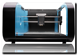 Yesterday, on a rather cold and wet afternoon, moto-abruzzo took a step into the future ……. courtesy of a good friend that I’m doing a project for. A 3D printer arrived! And being the top man that he is, he’s cool about me printing off those odd little Caponord bits-n-bobs.
It was rapidly unpacked and Jan and I stood in awe at this little box of awesomeness, we oooo’d and aaaah’d in all the right places …. then it was time to fire the beast up. But first a good nights rest. Early the next morning I loaded up a model and hit the ‘MAKE!’ button. My heart pounded as it hummed, rumbled and whired into action. For an hour it beavered away – then stopped dead! In fact everything stopped – ANOTHER BLOODY POWER CUT! So on with the coat and off to buy a UPS (Uninterruptible Power Supply) to keep computers and printers running when we get these annoying micro/mini power cuts that last no more than a second or two but mess everything up. Once installed I was away like a whippet on speed ……. by the end of the evening we  stood and marvelled at its first creation – A Mk1 speedo sensor case.
Like any piece of kit it has a bit of a learning curve attached to it, but hey, that’s all part of the fun. Here’s a pic of the first printed Capo speedo sensor main case and cap. The holes print really well even at this resolution and tap to M3 no problem. The sensor is a nice snug fit and (thankfully!) it fits in the brake caliper carrier and even the bolt lines up which is nice! So overall – moving in the right direction. Now I just need to order a couple of sensors, some cable, rubber boots and Molex connectors and the jobs as good as done. Then I can change out the sensor on the bike, run it around for a while and see how the printed parts hold up to life on a motorcycle.


Why bother with all this?
Have a look at the cost of a replacement sensor from Aprilia (AP8124985) ….. currently £112 plus postage from Fowlers and Ultimateparts in the UK and €146 (approx. £127) from wendelmotorraeder in Germany. OK it’s much cheaper from AF1 at £65 but the postage is higher and you may well have customs duty to pay – all bumping up the cost.
So …….. IF (a big ‘IF’ mind you) it tests OK over a couple of months and possibly a small batch were to be made, would anyone be interested in an aftermarket Capo speedo sensor for half the price of an original?
Anyway, until then what’s next ……. hmmmm.
- Hybrid velocity stacks – Caponord height with Futura diameter (51mm)
- Hi-Flo airbox snorkel
- Frame/axle/crash bar bungs (insects use the orifices as nesting sites!)
- ……. and maybe even a 1:5 scale model!! 😀
CGI dashboard – 2
Saturdays lovely sunny weather gave way to thick fog and a definite chill in the air – time then to hunker down on the PC and finish the CGI dashboard and add a couple of extra bits to make it a touch more interesting on the eye.
")
")
")
")
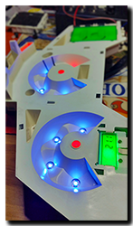
CGI dashboard – 1
 Slowly getting more parts of the Capo into CAD/3D …. finishing the dashboard motor off (after almost 2 years!) gave me the nudge to get the circuit board done. Here’s a work in progress, only a couple more chips to fit. Then the inlay and case / lens will see it polished off. Can I keep up the momentum or will galloping apathy step in … hmm who knows! 😕
 Capo charging system ….. a new page going up shortly with a fair bit of (new) info regarding alternator output, waveforms, voltage, current and how those are affected with the attachment of different technology regulators – plus how exactly those regulator-rectifiers do the job of producing rectified DC. Pitched at electrical newbies I’ll be running through each of the components and what they do electrically (hopefully) in a way that makes sense, including why some wires can be thin and work just fine and why some regulators get hot and others don’t.
Dashboard motors – an update
 An old (ironic) joke in England states that you will stand around for an eternity waiting for a bus – only for three to come along at the same time! In the same way, dashboard faults sometimes do a similar thing. Recently I had three boards arrive; all had defective speedo/tacho motors. All six motors were physically broken and two electrically dead.
The motors mount to the circuit board by four soldered pins and two push-fit pegs. The arms on the motor case that grip the pegs break off and that leaves the motor pivoting  on the four soldered pins. With time and vibration, the armature wires that are soldered to the pins flex and break – one dead motor.
Replacements are available from flea-bay for between £30 and £45 –not exactly a cheap part, especially when the old one may still be working fine. Now it seems a cheaper solution is available in the form of a replacement front cover (part with arms) for a fraction of the price of the full motor. On close inspection it doesn’t look like a 1-for-1 copy of the original (the arms are slightly different) but it’s well worth a punt at that price to see if it works.
So why are they failing? Well my guess is, it’s a combination of age, vibration and heat/cold cycling that causes the arms to fracture. Once that support has gone, the motor is left suspended on the four soldered arms – and they in turn are press-fitted into flimsy  plastic spacers. The armature wire (very thin!) is soldered onto these pins, with very little slack ……. So any flex between motor and pins will inevitably stress the wires and cause them to break. They can be repaired of course, you just need good equipment, a magnifier and VERY steady hands!
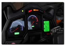
Unfortunately, spotting a broken motor is difficult without striping the dashboard, but here’s a little something to look out for …… have a good close look at the needle, where it passes through the inlay. If the speedo needle looks like it’s drooping downwards or the tacho needle looks like it’s leaning to the left – suspect a broken motor. Remove the dashboard and give it a gentle shake – hear something rattling inside? That’ll be the broken arms floating around – tick-tock, tick-tock – it’s only a matter of time now before the armature wires give way!

g this is fun!
 of the Capo") I’m not really enthusiastic about the constant onslaught of technology on motorcycles …. the cynic in me sees mostly a revenue-earning exercise whereby the benefits to you and me are far outweighed by the locked-out, take-it-to-the-dealer and be fleeced mentality of the manufacturers.
I’m not really enthusiastic about the constant onslaught of technology on motorcycles …. the cynic in me sees mostly a revenue-earning exercise whereby the benefits to you and me are far outweighed by the locked-out, take-it-to-the-dealer and be fleeced mentality of the manufacturers.
But occasionally I do spot something that tweaks the nose of my flagging interest …. this time it’s been the BMW Dynamic Brake Light system. Trying to get the myopic, half-asleep nit-wit to notice the difference between my normal braking and HARD BRAKING is sometimes a real issue. There’s nothing worse than gliding to a halt only to hear some plank with full ABS active about to kiss my back wheel! Hmmm so how hard can it be to make a box of tricks to do the same as the BMW system and fit it on the Capo …..
Well a tad more difficult than I first thought that’s for sure! The BMW system seems to work as follows:
- At speeds over 50Kmh(31mph) when braking HARD the brake light pulses at 5Hz*
- When the speed drops below 14Kmh(9mph) while still braking hard, the hazard lights are activated.
- When the speed rises back above 20Kmh(12mph) the hazards are turned off.
- At all other times the brake light functions as normal.
*EU rules quote a rate of 4Hz (±1Hz) for LED’s and 4Hz (-1Hz) for incandescent bulbs.
 So how to replicate this on the Capo? Enter one test-box to get things started …… a microcontroller that measures acceleration in three axis and has inputs/outputs to the brake light, hazard lights and speedometer. The box of tricks is designed to allow normal brake/hazard light function in case of power or hardware failure … all in the name of safety don’t ya know.
Getting usable data from the accelerometer was harder than I thought ….. the thing is VERY sensitive and has needed a lot of filtering and data-smoothing to get usable info from it. But after a couple of days and quit a few emergency stops (all good practice!) the data is starting to look good.
 Next up, I need to input the Capo’s speed to the microcontroller. For this I’ll use the speed output pin directly from the dashboard – I knew it would come in handy one day! All the inputs are buffered with opto-isolators to make sure the system is as well protected from the noisy fluctuating voltage in the Capo’s loom as is possible. Now with the prototype well under way, it just remains to find answers to some other questions ….. such as what about braking on wet, loose, icy surfaces where deceleration will be significantly less, but the dynamic brake light might still be useful. My guess is the BMW system has some integration with the ABS system to shift the triggering point, but I don’t have ABS! This one I’ll have to ponder on a while longer.
One things for sure …. you learn a lot about braking forces, motorcycle dynamics and breaking code doing this malarkey! Oh and I’ve found out that a warm front tyre breaks grip at about 1.1g …… 😳
Trippin’ all the way!
 Sometimes a particular feature of a piece of technology can drive you nuts – that itch you can’t scratch! Here’s my particular niggle with the Capo dashboard ……
Just imagine, it’s a nice day and you’re all suited-and-booted, ready to tear up the countryside on the Capo. You’ve pushed the ‘Set’ button on the dashboard to display the trip meter and all is fine and dandy in the world, later you pull over for a break and when you restart the bike – the dashboard has switched back to odometer! I know it’s not exactly the end of the world, but it is annoying. Why couldn’t Aprilia just code the damn thing to display on start-up what it showed at shut-down, many other bikes seem to do it.
So as part of the long running Mk2 dashboard project, the feature has now been incorporated!
With a little bit more code and a couple of extra wires, the dashboard now knows what was displayed (odometer or trip) at key-off. Then it simply electronically replaces a winter-gloved podgy finger and prods the ‘Set’ line to the old microcontroller a second after the board finishes its POST (power-on-self-test) routine. It also now reads the voltage from the fuel level sensor in the fuel tank, so that if the trip meter is displayed at key-off AND the fuel level changes from less than 15% to greater than 90% (approx. <5l to >20l refuel) at the next key-on, the trip meter will be reset automatically. If you don’t want the reset to go ahead, you simply make sure the dashboard is displaying the odometer before switching the bike off, now the reset is ignored.
Of course all this is well and good on the workbench, but in real day-to-day use – will it scratch that itch? Hmm, time and a few miles under the Capo’s belt will determine that answer……. maybe I’ll just end up with a nasty little rash! 😕
Flat-line dashboard
 With just over 82,000 miles on the Caponord, the dashboard died. Yes, while about to set off from a rather innocuous little shop car park on a hot and humid afternoon, the dashboard shuffled off its mortal coil … Curled up its toes, bought the farm – as dead as the proverbial Dodo.
On the way home I mulled over the possible cause, was it the additional microcontroller/hardware I added in 2013 or simply a failure of some part of the original Magneti Marelli circuit board? By the time I got home, I had a few possibilities rolling around my head, but nothing concrete. 15 minutes after cutting the ignition, the dashboard was on the test-bench.
Ultimately the fault was traced to a ‘Via’, a hole where a signal/power track passes from one side of the board to the other. In this case, where there should have been 12 Volts, there was 2 Volts! A simple wire link bypassed the problem and the dashboard popped back into life.
So is it a design flaw or manufacturing defect? I’d say probably a bit of both! Below is a photograph of the faulty area on a Mk1 and Mk2 board. Notice the Mk2 (right hand) has a much larger track area AND has 4 Via’s instead of the Mk1’s single Via bringing power from the top of the board to the underside. All well and good BUT both boards still only have a single Via (red dot) to pass power to the regulator on the front ……….. And it’s this Via that failed!

It seems that this was known to be a troubled area and was re-designed …. sort of. But the fact that the last Via was never upgraded, simply left this as the weak link – unfortunately, one of many on these boards!
Anyway, this one’s a runner for now ……. and that’s a jolly good excuse for a run around for an hour or two to thoroughly test it out! 😀