 When it comes to electrics/electronics, we are all oh-so familiar with the fact that for the most part, things either work or don’t. But occasionally we get the mighty frustrating intermittent fault that dances between the two, then we also get the rare as hens teeth, slow failure. The one that takes an absolute age to travel from 100% working to finally broken, the kind of behaviour more befitting a mechanical part than electrical. Well that’s what I’ve just had!
Back in August of 2010 I fitted the Shindengen FH012 rectifier / regulator and I think it’s fair to say that it began its slow decline within a couple of years. The once steady 14.2V at 4,000rpm slowly ebbed away, a few millivolts here, a few millivolts there, year on year. By last autumn the charging circuit was giving me about 13.6V (idle) and 13.9V at motorway speeds.
After the incident with the stuck starter solenoid a couple of weeks ago, it seemed to shave off another 0.1-0.2V. On the return leg of our trip the Sparkbright battery monitor would dip from green (OK) to amber (not OK!) when the fan cut in …… such that I was turning the headlights off when we hit slow traffic in order to keep the thing charging.
Each year I’d checked the alternator, wiring, connectors and battery and everything tested just fine …… so was it the regulator? Time would tell I figured! In January I bagged a brand new Shindengen FH008 but hadn’t got around (galloping laziness!) to trying it out. So before the main  power/ground cables were replaced it seemed only fit and proper to test the new regulator, then decide what to do about sorting the charging system.
The quickest test was to simply crimp some spades on the FH008 leads and plug them directly into the Furukawa sockets on the charging loom and see what happened – 14.4V (idle) and 14.5V at 4,000rpm is what happened! Most definitely the regulator rather than the alternator or wiring then.
The old loom was removed and inspected – all still in excellent condition. Even so, new cables, connectors and sheathing were ordered from the original suppliers and in went the FH008, back in the original location. With the bike buttoned up and a healthy voltage at the battery, it just left a moment for my eye to linger on the right hand side of the bike. Somehow it looks odd, naked, empty without the old rec/reg in front of the clutch, I’ll get used to it I know, but for now I do miss it!
Measured voltage at battery:
Idle (lights / fan OFF) – 14.4V and at 4K – 14.5V
Idle (lights ON + fog lights ON) – 14.3V and at 4K – 14.4V
Idle (lights / fan ON) – 13.9V and at 4K – 14.2V
Idle(lights / fan / fog lights + everything else* ON) – 12.8V and at 4K – 13.6V
* GPS / Intercom / K1 Camera / Heated Grips (high) / Cruise Control / brake lights


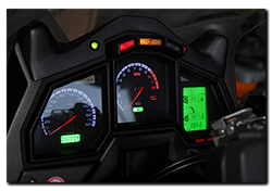 With just over 82,000 miles on the Caponord, the dashboard died. Yes, while about to set off from a rather innocuous little shop car park on a hot and humid afternoon, the dashboard shuffled off its mortal coil … Curled up its toes, bought the farm – as dead as the proverbial Dodo.