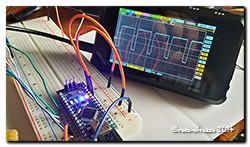
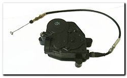
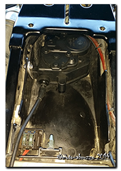
 Hi all ….. a quick post about the cruise control and a word of caution!
I finally got the cruise control servo unit mounted into the tool-tray of the Capo today. A relatively straight forward job, requiring only a minor rework of one of the mounting lugs, a new bracket fabricating and a couple of holes drilled in the under-tray.
The old throttle cable was removed from the unit and a new 6mm Teflon lined sheath fitted ready to run forward to the throttle bodies. It fits a treat down the side of the two 30A fuses and there’s already a cut-out in the undertray for it to run through, talk about made for the job! I’ll refit the old in-line adjuster and look at routing it along the engine/throttle bodies next week. So far so good!!! 😀
And so everything had gone beautifully, with a final firm slap the rear seat was locked in place …………. Only to realise that the key would no longer release it! Yes the dreaded can’t-remove-the-rear-seat syndrome. My fault entirely, as I should have checked the cable-outer was secure at the latch when I put the luggage rack/deck back in place. So here for your info is how to sort out what seems a very daunting situation to be in. Others may have a different technique, but this one worked for me.
Firstly stop twisting the key harder and harder, while bashing the seat in a vein hope it will pop off ….. it won’t ….. The noise you can hear when you turn the key is simply the cable outer and spring moving – NOT the latch.
Secondly, remove the rear deck bolts (x4). Of course you may have to remove a topbox and associated mounting plate first – no one said it was going to be easy! Now grip the deck just above the rear light and lift, at the same time slide something like a ½” drive 12” extension into the gap to hold the deck up. You’ll need to get the extension right the way in, enough to expose the latch mechanism. With the mechanism visible, slide a flat bar or long screwdriver in and gently push on the tab where the cable end is visible – from the rear of the bike, push to the left. And you should hear a satisfying click as the seat pops up. Reseat the cable-outer, reassemble the bike and sink a cold beer, you’ve earned it!
What a muppet …. anyway, I hope you’ve learned a little something from my foolishness and don’t make the same mistake!
……. now to connect the servo unit to the throttles.


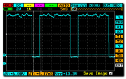
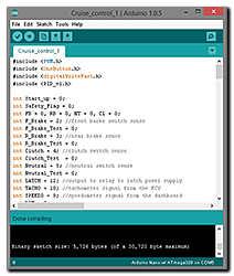 The system I’m thinking about will, when all parameters are met (speed, revs etc) lock onto the chosen speed when the ‘Set’ button is pressed. The microcontroller will then look at the error between the chosen speed and actual speed and adjust the throttle as neccessary to try and maintain the error at zero – this is done using PID (